I use a Raspberry Pi to control a PWM fan in one of my comms racks, and I wanted to monitor the fan’s speed using its tachometer signal. This guide will use a kernel module to count the tachometer pulses and present it to telegraf, which can then be visualized in Grafana; as well as some basic PWM fan control. This is more of an advanced guide, you should probably look at the DriftKingTW’s guide if you’re unsure what you’re doing.
Hardware Setup
On most computer fans, the first 2 pins are for power and ground, the third pin is the tachometer signal, and PWM fans have a fourth pin for speed control. Power and ground can be connected to the Raspberry Pi’s 5V and GND pins, or wherever you are powering the fan from. The tachometer pin can be connected to any GPIO pin on the Raspberry Pi, and the PWM pin can be connected to a hardware PWM pin.
I am using a Noctua NF-A12x25-5V-PWM, and it is connected as follows:
| Fan Pin | Raspberry Pi Pin |
|---|---|
| 1 (Power) | 5V |
| 2 (Ground) | GND |
| 3 (Tachometer) | GPIO 23 |
| 4 (PWM) | GPIO 18 |
You will also need a pull-up resistor on the tachometer pin, as it is an open collector output. I used a 10k resistor between the tachometer pin and 3.3V, but as the Noctua white paper states the max current is 5mA, any reasonable resistor above 660 ohms should work.
Installing the Kernel Module
Using a kernel module is the most efficient way to read the tachometer signal, as any other way will require a hand off to user space, and I wanted to avoid that overhead even if it’s only interrupting ~60 times a second. I will be using rszimm’s gpio-counter module, which will count the pulses and expose the count via a sysfs interface.
-
Install the required packages: You will need the kernel headers and build tools to compile the module.
sudo apt update sudo apt install raspberrypi-kernel-headers build-essential -
Clone the gpio-counter repository
git clone https://github.com/rszimm/gpio-counter.git cd gpio-counter -
Add a DKMS config: This will allow the module to be automatically rebuilt when the kernel is updated.
Create a file named
dkms.confwith the following content:PACKAGE_NAME="gpio-counter" PACKAGE_VERSION="1.0" AUTOINSTALL="yes" # Module(s) to build BUILT_MODULE_NAME[0]="gpio-counter" # Source and build locations DEST_MODULE_LOCATION[0]="/extra" MAKE[0]="make -C ${kernel_source_dir} M=${dkms_tree}/${PACKAGE_NAME}/${PACKAGE_VERSION}/build" CLEAN="make -C ${kernel_source_dir} M=${dkms_tree}/${PACKAGE_NAME}/${PACKAGE_VERSION}/build clean" -
Add the module to DKMS
 sudo dkms add .
 sudo dkms build gpio-counter/1.0
 sudo dkms install gpio-counter/1.0
Configuring the Kernel Module
-
Finding your GPIO pin gpio-counter uses kernel GPIO numbering, you can use the following command to list the GPIO pins and their numbers. On my Pi 5 GPIO23 is
594.cat /sys/kernel/debug/gpio -
Load the module: You can load the module with the following command, replacing
GPIO_PINwith the GPIO pin number you found in the previous step.sudo modprobe gpio-counter gpio_pins=GPIO_PIN -
Check the sysfs interface: The module will create a sysfs interface at
/sys/kernel/gpio-counter/0/pulse_count. You can check the current count with:cat /sys/kernel/gpio-counter/0/pulse_count -
Make the module load on boot: To ensure the module loads on boot, you can create a file in
/etc/modules-load.d/and add the module name to it. You should also create a modprobe configuration file to set the GPIO pin.echo gpio-counter | sudo tee /etc/modules-load.d/gpio-counter.conf echo options gpio-counter gpio_pins=GPIO_PIN | sudo tee /etc/modprobe.d/gpio-counter.conf
Configuring Telegraf
-
Creating a long running script: To calculate the fan RPM, I created a simple bash script at
/opt/count_fan_speed.sh. It will read the pulse count, then wait for a new line from STDIN, then get a second pulse reading, calculate the RPM based on the time interval and pulse count difference, and output it in a format suitable for Telegraf.#!/usr/bin/env bash SYSFS="/sys/kernel/gpio-counter/0/pulse_count" PPR=2 # Pulses per revolution (usually 2) while true; do timestamp1=$(date +%s%3N) count1=$(<"$SYSFS") read -r timestamp2=$(date +%s%3N) interval_ms=$((timestamp2 - timestamp1)) count2=$(<"$SYSFS") delta=$((count2 - count1)) # counter wrapped around if [ "$delta" -lt 0 ]; then delta=0 continue fi # RPM = delta * 60000 / (interval_ms * PPR) if [ "$interval_ms" -gt 0 ]; then rpm=$(( delta * 60000 / (interval_ms * PPR) )) else rpm=0 fi echo "rack_fan,location=upstairs rpm=$rpm" done -
Configuring Telegraf: Add this snippet to your Telegraf configuration file (usually located at
/etc/telegraf/telegraf.conf):[[inputs.execd]] command = ["/opt/count_fan_speed.sh"] signal = "STDIN" data_format = "influx" -
Configure Grafana: There are lots of ways to query this data in Grafana, but you will basically need to query the
rack_fanmeasurement and use therpmfield, and group by thelocationtag if you have multiple fans. Here’s a screenshot of my fan speed graph in Grafana: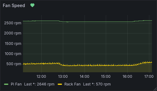
Basic PWM Fan Control
For PWM fan control, you will need a 4 pin fan, as 3 pin fans do not have a PWM control pin.
I created this basic script at /opt/fan_control.sh to control the fan speed, you may need to change the sysfs path for your Pi model and GPIO pin:
#!/usr/bin/env bash

MIN_TEMP=40000  # 40.000 C
MAX_TEMP=80000  # 80.000 C

INTERVAL=1  # 1 Second interval between checking temperatures

PWM_PERIOD=40000  # 25KHz
TEMP_MUL=$(($PWM_PERIOD / ($MAX_TEMP - $MIN_TEMP)))

echo 2 > /sys/class/pwm/pwmchip0/export  # Export pwm2 to sysfs
echo $PWM_PERIOD > /sys/class/pwm/pwmchip0/pwm2/period  # Set PWM Period
echo $PWM_PERIOD > /sys/class/pwm/pwmchip0/pwm2/duty_cycle  # Set Duty Cycle to max as failsafe
echo 1 > /sys/class/pwm/pwmchip0/pwm2/enable  # Enable PWM

while :; do
    temp=$(< /sys/class/thermal/thermal_zone0/temp)

    if (($temp < $MIN_TEMP)); then
        duty=0
    elif (($temp > $MAX_TEMP)); then
        duty=$PWM_PERIOD
    else
        duty=$((($temp - $MIN_TEMP) * $TEMP_MUL))
    fi

    echo $duty
    echo $duty > /sys/class/pwm/pwmchip0/pwm2/duty_cycle

    sleep $INTERVAL
done
I also created a systemd service at /lib/systemd/system/fan_control.service to run this script on boot:
[Unit]
Description=PWM Fan Control

[Service]
Type=simple
TimeoutStartSec=0
Restart=on-failure
RestartSec=30s
ExecStart=/opt/fan_control.sh

[Install]
WantedBy=multi-user.target
You can also add the duty cycle percent to telegraf script that I created at /opt/count_fan_speed.sh:
#!/usr/bin/env bash
SYSFS="/sys/kernel/gpio-counter/0/pulse_count"
PPR=2  # Pulses per revolution (usually 2)

SYSFS_PERIOD="/sys/class/pwm/pwmchip0/pwm2/period"
SYSFS_DUTY="/sys/class/pwm/pwmchip0/pwm2/duty_cycle"

while true; do
  timestamp1=$(date +%s%3N)
  count1=$(<"$SYSFS")
  read -r
  timestamp2=$(date +%s%3N)
  interval_ms=$((timestamp2 - timestamp1))
  count2=$(<"$SYSFS")
  delta=$((count2 - count1))
  # counter wrapped around
  if [ "$delta" -lt 0 ]; then
    delta=0
    continue
  fi
  # RPM = delta * 60000 / (interval_ms * PPR)
  if [ "$interval_ms" -gt 0 ]; then
    rpm=$(( delta * 60000 / (interval_ms * PPR) ))
  else
    rpm=0
  fi

  period=$(<"$SYSFS_PERIOD")
  duty=$(<"$SYSFS_DUTY")
  percent=$(( duty*100 / period ))

  echo "rack_fan,location=upstairs rpm=$rpm,duty=$percent"
done
Other Resources
- DriftKingTW has written a much better guide with pictures, however they are using RPi.GPIO for everything, instead of handling stuff in kernel.
- The Noctua PWM white paper is a really good read if you want to understand how PWM fans work: Noctua PWM White Paper.
Thanks for reading!
Steve.
Comments
Replyfroggs Nov 18, 2025
It did not work for me. Got this error when I got to this step ~ $ sudo modprobe gpio-counter gpio=535 modprobe: ERROR: could not insert 'gpio_counter': Invalid argument
ReplySteve-Tech Nov 18, 2025
Hmm okay, are there any errors in
Replydmesg? Also what board are you using and what GPIO pin are you targeting? (535 isn't valid on my Pi 5)Smeghead Mar 26, 2026
For what it's worth, I see the same error message that froggs encountered. It appears that the module has changed; according to
Replymodinfo gpio-counter, the parameter is now calledgpio_pins, and is a comma-separated list of pin numbers. Additionally, I think there's also a potential initialisation problem involved in using GPIO23 as-is. By default, I believe that the GPIO pins <= 8 are set high by default, and the rest low. Since the tach signal pulls down to ground, this realistically needs to use the likes of GPIO8 (not used by default?) or have a step to set the state of the pin, as GPIO23 always reads low on my pi 4. With GPIO8 and no other tweaks, I'm getting a signal from a fan I'm testing.Smeghead Mar 26, 2026
Oh, I also forgot: since the module can now take multiple pins, the sysfs interface also changed, with
Reply/sys/kernel/gpio-counter/0/pulsecountshowing the count for the first pin listed,/sys/kernel/gpio-counter/1/pulsecountthe next, etc. Even with only a single pin specified, the sysfs interface is still at.../0/pulse_count.Steve-Tech Mar 27, 2026
Thanks for the heads up! I've just updated the article for the latest commit of gpio-counter. I also forgot to mention this before, but I had a 10k pull up resistor, which explains the GPIO reading low.
Reply